
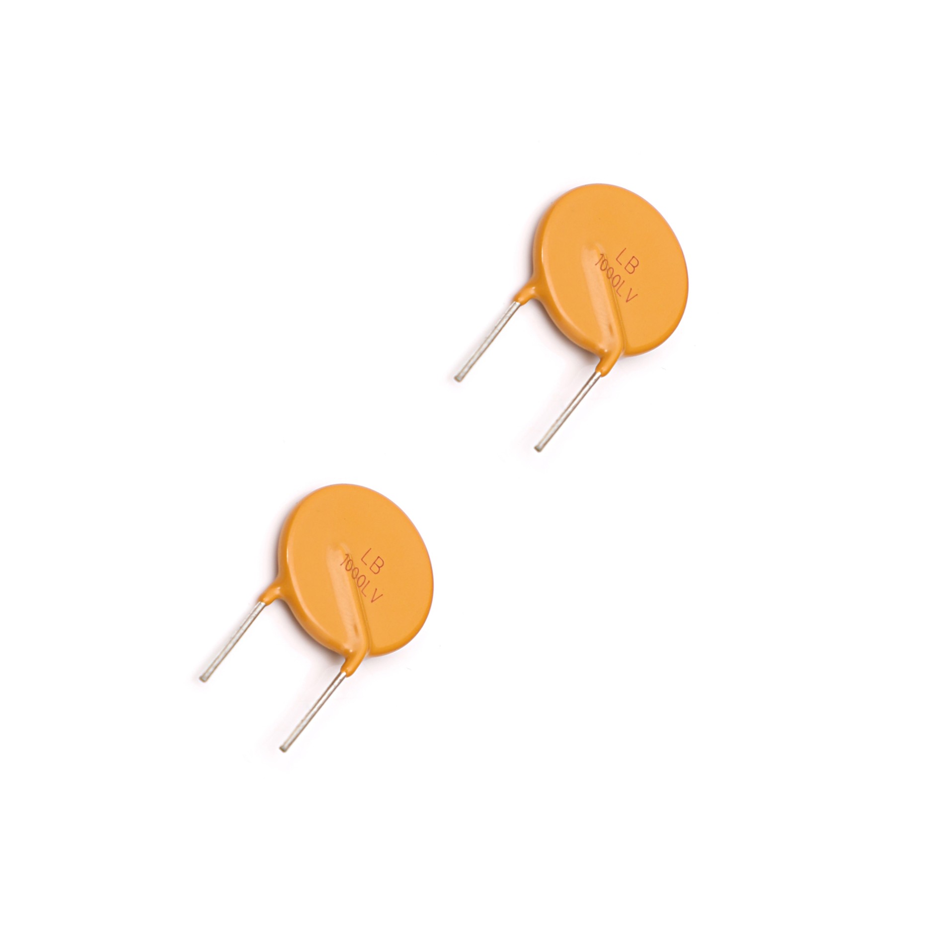
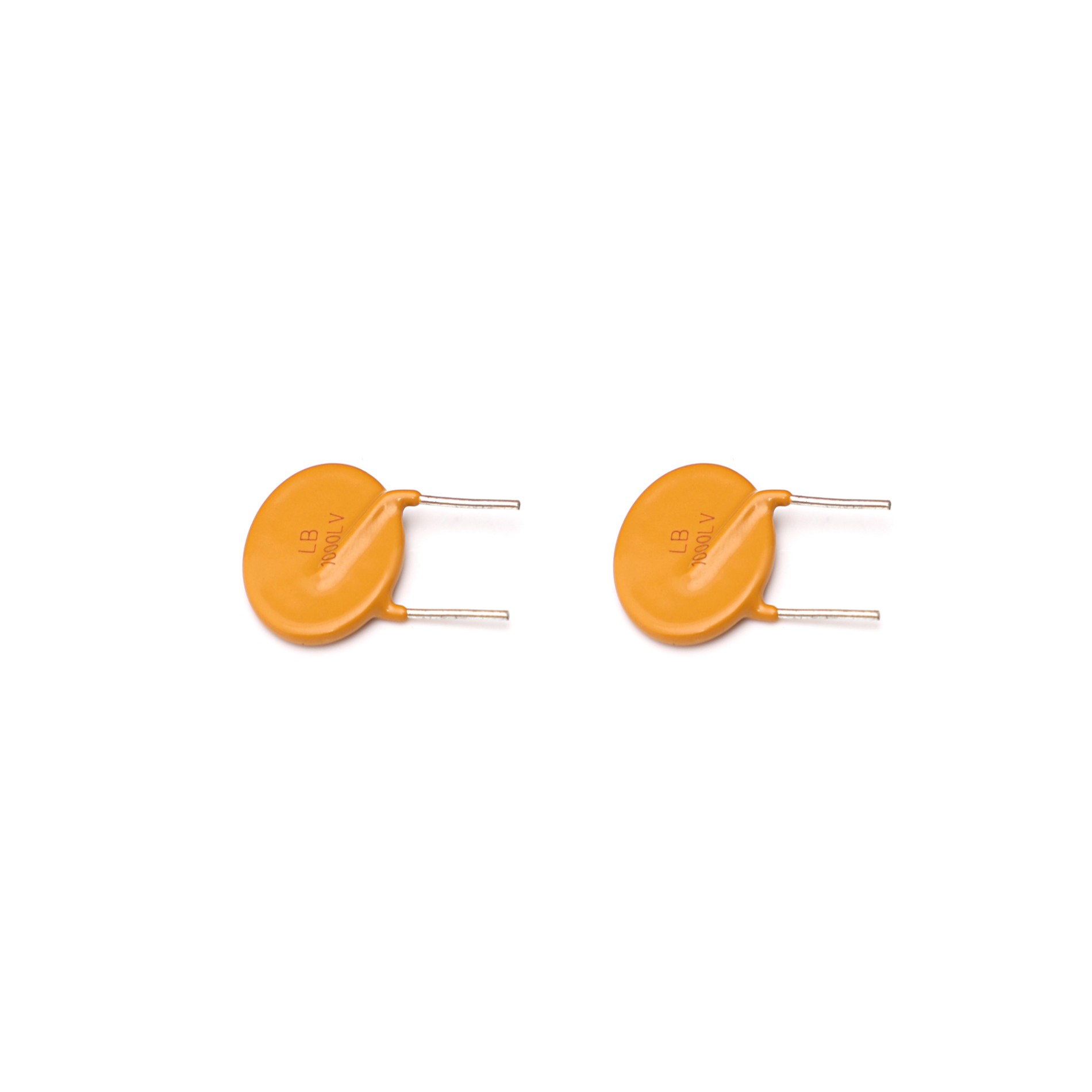
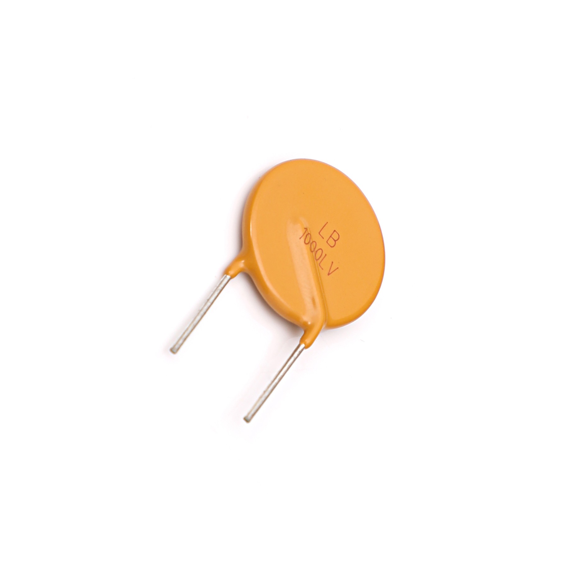
Radiale leiding PPTC resetbare zekering
: Songshan
: Sjanghai
: 7-15 dagen
: 15000000
LB050LVF is een polymeerherstelbare zekering. Bij een hoge temperatuur en een hoogspanningstoestand, wordt de zekering gemaakt door een speciale technologie nadat het hoog-moleculair organisch polymeer en geleidend deeltjesmateriaal goedkeurt. De zekering kan zichzelf resetten en kan herhaaldelijk worden gebruikt nadat deze om een of andere reden is gesprongen. De uitvoering zal niet vervallen ondanks de constant herhaalde tijden. De zekering kan meer dan duizend keer worden gereset en dus worden de kosten in grote mate bespaard. In het circuit kan de zekering worden gebruikt als een thermische zekering. Daarom toont het tot op zekere hoogte de prestaties van de thermische zekering in het circuit en wordt het de rol van thermische zekering.
(EEN)
(EEN)(V)
(EEN)(EEN)
(S)(W)
(Ω)(Ω)
Dimensie
LB050LVF0.05
0.121.0
0.2515.0
-18.50
65.00
Fig.3
LB080LVF
0.08
0.19
1.2
| 0,40 | |||||
15.0 | - | 7.40 | 26.00 | Fig.3 | LB250LVSF | |
0.25 | 0.56 | 3.5 | 1.25 | 18.5 | - | |
1.30 | 3.80 | Fig.5 | LB550LVF | 0.55 | 1.25 | 7.0 |
2.75 | 26.0 | - | 0.45 | 1.45 | Fig.5 | LB800LVF |
0.80 | 1.80 | 10.0 | 4.00 | 40.0 | - | 0.30 |
1.32 | Fig.5 | LB1000LVF | 1.00 | 2.00 | 10.0 | 5.00 |
21,0 | - | 0.22 | 0.58 | Fig.3 | IH = Hold-stroom: maximale stroom waarbij het apparaat niet zal trippen bij 25 ° C stilstaande lucht. | IT = uitschakelstroom: minimale stroomsterkte waarop het apparaat altijd zal trippen bij 25 ° C stilstaande lucht. |
Vmax = Maximum voltage-apparaat is bestand tegen beschadiging bij nominale stroom. | Imax = Maximaal foutstroomapparaat kan bestand zijn tegen beschadiging bij nominale spanning. | Ttrip = Maximale tijd om te trippen op toegewezen stroom. | Pdtyp = Typische vermogensdissipatie: typische hoeveelheid stroom die door het apparaat wordt afgevoerd in de luchttoestand. | Rmin = minimale apparaatweerstand op 25 ℃ voorafgaand aan trippen. | R1max = maximale apparaatweerstand gemeten na 1 uur na eenmalige rit. | Part Numbering System |


Testprocedures en vereistenTestTest voorwaarden
Criteria accepteren / verwerpen
| Weerstand | ||||||||
In stilstaande lucht @ 25 ℃ | Rmin≤R≤Rmax | Tijd om te reizen | Opgegeven stroom, Vmax, 25 ℃ | T≤maximum tijd tot trip | Houd stroom | 30min, bij IH | Geen reis | Reiscyclus | |
Vmax, Imax, 100cycles | Geen vonkvorming of verbranding | Trip-uithoudingsvermogen | Vmax, 24 uur | Geen vonkvorming of verbranding | Toepassing | Vereisten | Aanbeveling voor soldeer: | * | Methoden: IR, dampfaseoven, heteluchtoven, golfsoldeer, soldeertemperatuur mogen het GB-T2423-verzoek niet overschrijden. |
* Apparaten kunnen worden gereinigd met behulp van standaard industriële methoden en oplosmiddelen. | Opmerkingen: | Als de terugvloeitemperaturen het aanbevolen profiel overschrijden, voldoen de apparaten mogelijk niet aan de prestatievereisten. | opslagruimte | : | De maximale omgevingstemperatuur mag niet hoger zijn dan 40 ℃. Opslagtemperaturen hoger dan 40 ℃ zouden kunnen resulteren in de vervorming van verpakkingsmaterialen. De maximale relatieve vochtigheid aanbevolen voor opslag is 70%. Hoge vochtigheid bij hoge temperatuur kan de oxidatie van het soldeerplateren op de afsluiting versnellen en de soldeerbaarheid van de componenten verminderen. Verzegelde plastic zakken met droogmiddel moeten worden gebruikt om de oxidatie van de afsluiting te verminderen en mogen alleen voor gebruik worden geopend. De producten mogen niet worden opgeslagen in gebieden waar schadelijke gassen die zwavel of chloor bevatten aanwezig zijn. | Waarschuwing: | PPTC-apparaten zijn bedoeld voor bescherming tegen incidentele overstroom- of foutsituaties bij oververhitting en mogen niet worden gebruikt wanneer wordt verwacht dat meerdere storingen optreden. Gebruik buiten de maximale waarderingen of oneigenlijk gebruik kan resulteren in beschadiging van het apparaat en mogelijke elektrische vonkontsteking en vlammen. | Opmerkingen: | De specificatie is bedoeld om applicatie-, product- en technische gegevens te presenteren om de gebruiker te helpen bij het selecteren van PPTC-circuitproductieapparaten. Gebruikers moeten echter onafhankelijk de geschiktheid van elk product evalueren en testen. Wayon geeft geen garanties met betrekking tot de nauwkeurigheid of volledigheid van de informatie en wijst elke aansprakelijkheid af die voortvloeit uit het gebruik ervan. Wayon's enige verplichtingen zijn die in de Wayon Standaard Verkoopvoorwaarden en Wayon is in geen geval aansprakelijk voor enige incidentele, indirecte of vervolgschade die voortvloeit uit de verkoop, wederverkoop of misbruik van haar producten. Wayon behoudt zich het recht voor om informatie zonder kennisgeving te wijzigen of bij te werken in deze specificatie. |
LB250LVSF | 0.40 | 0.37 | 0.31 | 0.25 | 0.20 | 0.17 | 0.15 | 0.12 | 0.08 |
LB550LVF | 0.93 | 0.82 | 0.69 | 0.55 | 0.47 | 0.41 | 0.36 | 0.30 | 0.23 |
LB800LVF | 1.45 | 1.24 | 1.00 | 0.80 | 0.65 | 0.58 | 0.52 | 0.45 | 0.38 |
LB1000LVF | 1.60 | 1.42 | 1.23 | 1.00 | 0.78 | 0.69 | 0.61 | 0.54 | 0.42 |
Electrical Characteristics at 25℃
Part number
| IH | IT | Vmax | Imax | Max. Time-to-trip | Pd typ | Rmin | R1max | Figures for | |
(A) | (A) | (V) | (A) | (A) | (S) | (W) | (Ω) | (Ω) | Dimension | |
LB050LVF | 0.05 | 0.12 | 265 | 1.0 | 0.25 | 15.0 | - | 18.50 | 65.00 | Fig.3 |
LB080LVF | 0.08 | 0.19 | 265 | 1.2 | 0.40 | 15.0 | - | 7.40 | 26.00 | Fig.3 |
LB250LVSF | 0.25 | 0.56 | 265 | 3.5 | 1.25 | 18.5 | - | 1.30 | 3.80 | Fig.5 |
LB550LVF | 0.55 | 1.25 | 265 | 7.0 | 2.75 | 26.0 | - | 0.45 | 1.45 | Fig.5 |
LB800LVF | 0.80 | 1.80 | 265 | 10.0 | 4.00 | 40.0 | - | 0.30 | 1.32 | Fig.5 |
LB1000LVF | 1.00 | 2.00 | 265 | 10.0 | 5.00 | 21.0 | - | 0.22 | 0.58 | Fig.3 |
IH=Hold current: maximum current at which the device will not trip at 25℃ still air.
IT=Trip current: minimum current at which the device will always trip at 25℃ still air.
Vmax=Maximum voltage device can withstand without damage at rated current.
Imax=Maximum fault current device can withstand without damage at rated voltage.
Ttrip=Maximum time to trip at assigned current.
Pdtyp=Typical power dissipation: typical amount of power dissipated by the device when in state air environment.
Rmin=Minimum device resistance at 25℃ prior to tripping.
R1max=Maximum device resistance measured after 1 hour post one-time trip.
Part Numbering System

Test Procedures And Requirements
Test | Test Conditions | Accept/Reject Criteria |
Resistance | In still air @ 25℃ | Rmin≤R≤Rmax |
Time to Trip | Specified current, Vmax, 25℃ | T≤maximum Time to Trip |
Hold Current | 30min, at IH | No trip |
Trip Cycle Life | Vmax, Imax, 100cycles | No arcing or burning |
Trip Endurance | Vmax, 24hours | No arcing or burning |
Application Requirements
Soldering recommendation:
* Methods: IR, Vapor phase oven, hot air oven, wave solder, soldering temperature should not exceed GB-T2423 request.
* Devices can be cleaned using standard industry methods and solvents.
Notes:
If reflow temperatures exceed the recommended profile, devices may not meet the performance requirements.
Storage:
The maximum ambient temperature shall not exceed 40℃. Storage temperatures higher than 40℃ could result in the deformation of packaging materials. The maximum relative humidity recommended for storage is 70%. High humidity with high temperature can accelerate the oxidation of the solder plating on the termination and reduce the solderability of the components. Sealed plastic bags with desiccant shall be used to reduce the oxidation of the termination and shall only be opened prior to use. The products shall not be stored in areas where harmful gases containing sulfur or chlorine are present.
Warning:
PPTC devices are intended for protection against occasional over-current or over-temperature fault conditions, and should not be used when repeated fault conditions are anticipated. Operation beyond maximum ratings or improper use may result in device damage and possible electrical arcing and flame.
Notes:
The specification is intended to present application, product and technical data to assist the user in selecting PPTC circuit production devices. However, users should independently evaluate and test the suitability of each product. Wayon makes no warranties as to the accuracy or completeness of the information and disclaims any liability resulting from its use. Wayon`s only obligations are those in the Wayon Standard Terms and Conditions of Sale and in no case will Wayon be liable for any incidental, indirect, or consequential damages arising from the sale, resale, or misuse of its products. Wayon reserves the right to change or update, without notice, any information contained in this specification.